Assembly Basics
Introduction
This article gives details about assembly programming for the Intel 8086 microprocessor. It also presents very clear details by providing example cases, definitions and syntax explanations on arithmetic instructions, logical instructions and operands.
Why study this topic? It’s important to understand the basic concepts of computer architecture, chip logic and memory management. People dealing with malware will also find it useful. Irrespective of the type of high-level language being used, before the code gets translated to machine code, it first must be translated into assembly language. This makes assembly language still important despite the evolution of high-level languages.

Become a certified reverse engineer!
Assembly language
An assembly language is a low-level programming language designed for a specific type of hardware processor. This low-level language is developed using mnemonics. Prior to writing a program in assembly language, it is necessary to have sufficient knowledge of the hardware for the controller or processor.
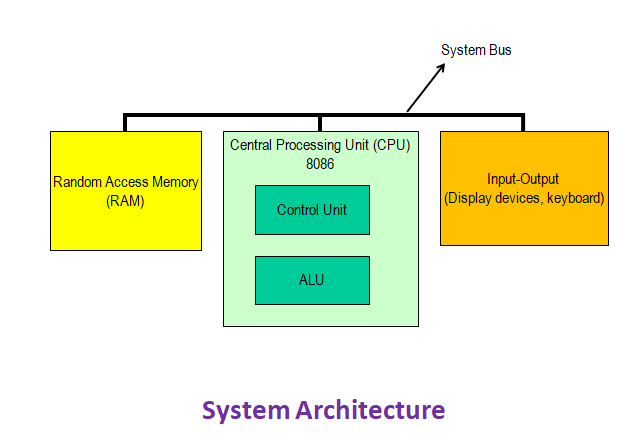
Figure 1
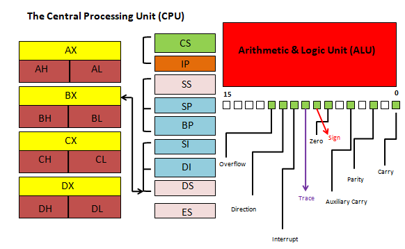
Figure 2
The 8086 processor architecture
As discussed on Elprocus, the architecture for the 8086 microprocessor is based on complex instruction set computing (CISC). This means the microprocessor has the capacity to perform multi-step operations or addressing modes within one instruction set. CISC is a CPU design where one instruction works several low-level acts such as memory storage, loading from memory and an arithmetic operation.
Registers
So that it can store information (under different values and different sizes), each processor is composed of different parts, “boxes,” called registers.
Syntax
LABEL: INSTRUCTION ; COMMENT
The label is just an address identifier
Labels
A label can be placed at the beginning of a statement. During assembly, the label is assigned the current value of the active location counter and serves as an instruction operand.
Comments begin with a semicolon (;) and do not generate machine codes. In other words, they are not translated.

Figure 3
Operands
In assembly language, the operand is the value upon which the opcode operates on.
From Figure 3, AL and 4Dh are operands.
The first operand AL is the destination and the second operand 4Dh is the source.
Arithmetic instructions
The arithmetic instructions for 8086 include addition, subtraction, multiplication, division, comparison, negation, increment and decrement.
For the remaining part of this article, all instructions will be executed using the EMU8086 version 4.08 software.

Figure 4
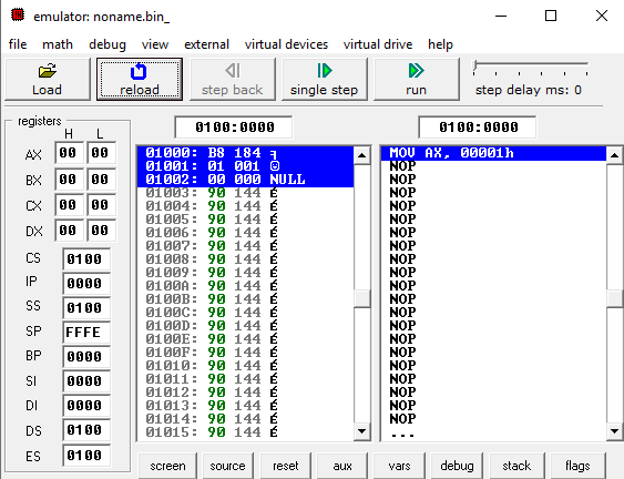
Figure 5
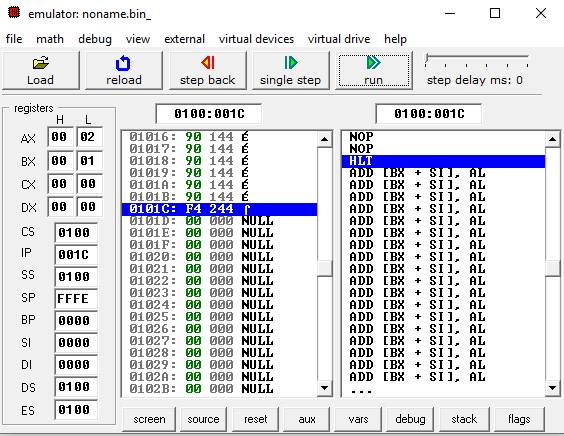
Figure 6
From Figure 4, the instructions on lines 01 and 02 initialized registers AX and BX with value of 01h. The next instruction added the values in register AX and register BX, and then stored the final value in register AX.
Figure 5 shows the high and low bytes (AH and AL) of the AX register. Their initial values were 0h before the arithmetic operation.
Figure 6 shows the high and low bytes (AH and AL) of the AX register after the instruction has been executed. The instruction on line 01 from Figure 4 initialized register AX with a value of 01h. The instruction on line 02 from Figure 4 initialized register BX with a value of 01h. The low byte of register AX assumes a final value of 02h after the instruction was executed.
In the next example of arithmetic instruction, we shall initialize registers BX and CX with hexadecimal values 4Dh and 30h respectively. The final instruction will add the values in BX and CX and then store it in BX.
Let’s analyze the instructions before we execute in the emulator. BX takes on the value 4Dh, which equals 77 in decimal. CX takes on the value 30h, which equals 48 in decimal. The sum, 7Dh (125 in decimal), is stored in BX.

Figure 7
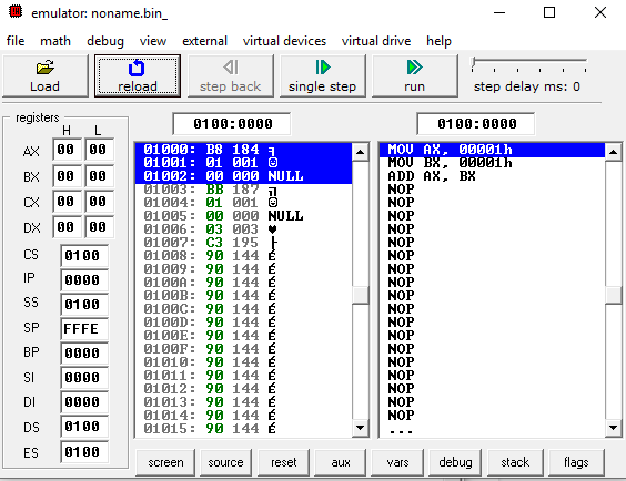
Figure 8
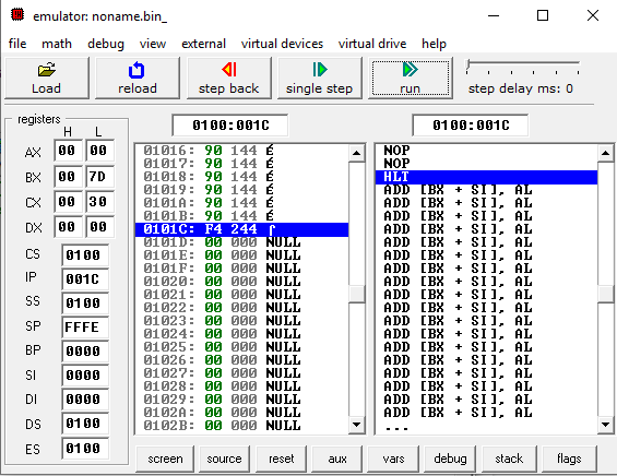
Figure 9
The screenshots in Figures 7 to 9 confirm the analysis we made. Register BX has the final value 7Dh.
Logical instructions
The 8086 processor instruction set provides the instructions OR, TEST, AND, XOR and NOT Boolean logic. The instruction can be used for testing a zero bit and setting or resetting a bit according to the requirements of the instruction.
The AND instruction
The AND instruction in 8086 performs a bitwise AND operation. The bitwise AND operation returns 1 if the matching bits from both the operands are 1; otherwise, it returns 0. Let's look at the logical truth table for the AND operation.
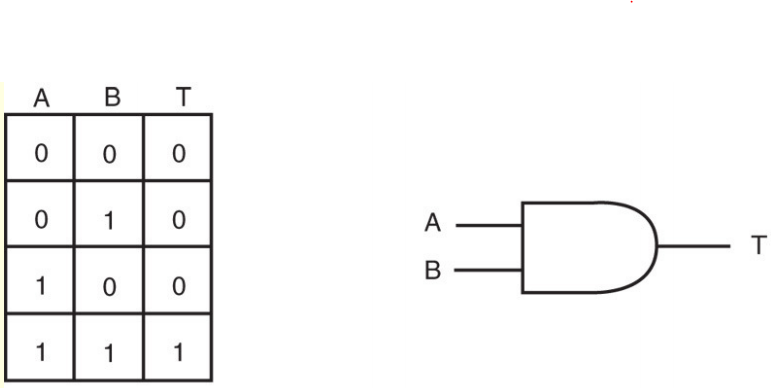
Figure 10
Following the truth table in Figure 10, the AND instruction will only return 1 if the bits in both operands are 1.
For this lab, we shall use the AND operation to clear the high order bits in the 16-register BX. To achieve this, we shall initialize BX with the binary value 00000011 00001111b (3Fh or 63decimal). Following from the truth table in Figure 10, we only need to AND BX with value 00000000 00001111b (0Fh or 15decimal) in order to clear its high order bits. If the AND instruction executes successfully, BH must be set to 0000 0000 and BL must be set to 0000 1111.

Figure 11
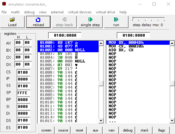
Figure 12
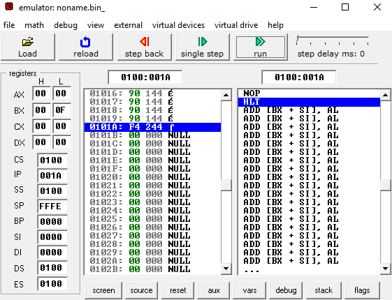
Figure 13
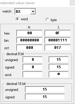
Figure 14
Figures 11 to 14 confirms the AND operation has executed successfully. The decimal value in BX, as shown in Figure 14, is 15 (0Fh). The high order bits in register BH have been set to 0000 0000b and the low order bits remain unaffected — 0000 1111b.
Conclusion
This article has explained the computer architecture in reference to the 8086 microprocessor hardware. It has also given fine details on arithmetic and logical instructions used in the 8086 processor by going as far as looking into initial values in registers and the final values after instructions are executed.
As you can see, assembly language is still a relevant programming language despite the evolution of high-level languages.


