VLAN network segmentation and security- chapter five [updated 2021]
This is Chapter 5 in Tom Olzak‘s book, “Enterprise Security: A practitioner’s guide.”
Chapter 4 is available here: Attack Surface Reduction – Chapter 4
Chapter 3 is available here: Building the Foundation: Architecture Design – Chapter 3
Chapter 2 is available here: Risk Management – Chapter 2
Chapter 1 is available here: Enterprise Security: A practitioner’s guide – Chapter 1
In Chapter 4, we examined system attack surface reduction. The next step is moving out from systems to the network attack surface. Traditional flat networks present a single surface to the outside and almost nothing to internal threats. By segmenting a network, and applying appropriate controls, we can break a network into a multi-layer attack surface that hinders threat agents/actions from reaching our hardened systems.
In this chapter, we step through a description of VLAN technology, how to secure it (including basic switch security), and how to control packets to increase the overall strength of attack surface defense. I use the term packet instead of frame to refer to transmission entities at both the network and the data link layers.
Why segmentation is important?
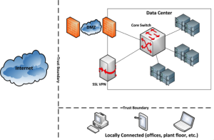
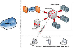
Traditional networks resemble Figure 5-1. Perimeter defenses protect the data center from external threats with little protection against internal threat agents. Once on the wire, an attacker has free access to system attack surfaces. No system attack surface defense is perfect; eliminating unwanted access significantly reduces the risk of a system breach.
In our example, the trust boundaries are located either on or external to the data center perimeter. A DMZ and SSL VPN appliance provide protection from unauthorized access, but they do little once a threat agent enters the data center network. Locally connected devices have full access to the data center network once the user authenticates. The assumption here is that perimeter controls prevent unauthorized access to system attack surfaces… a bad assumption.
Finally, the flat data center network is one large broadcast domain. Any device sending an ARP broadcast looking for an IP address in the data center will receive a reply if the address is assigned to an active server or other device. In other words, an attacker can see all servers in the data center. This provides potential access to every system attack surface. With enough time and the right skills, it is only a matter of time before a targeted attack surface cracks.
Figure 5 - 1: Flat Network - Single Broadcast Domain
Network segmentation with virtual local area networks (VLANs) creates a collection of isolated networks within the data center. Each network is a separate broadcast domain. When properly configured, VLAN segmentation severely hinders access to system attack surfaces. It reduces packet-sniffing capabilities and increases threat agent effort. Finally, authorized users only “see” the servers and other devices necessary to perform their daily tasks.
Another advantage of segmentation is protocol separation. Network architects can limit certain protocols to certain segments of the enterprise. For example, if IPX or AppleTalk systems exist on your wire, they can each have their own VLAN in which to operate. This limits traffic in each VLAN to relevant packets.
Finally, the use of VLANs enables secure, flexible user mobility. For example, a user assigned to a specific VLAN will always connect to that VLAN regardless of location. This is particularly helpful when designing wireless constraints. This requires, however, that you have something like 802.1x running for port authentication.
With 802.1x, you can use a RADIUS server and your user groups in LDAP or Windows Active Directory to assign the appropriate VLAN dynamically to the user or device. Otherwise, a user finding a statically configured port assigned to another VLAN can gain access simply by plugging in. Most wireless systems assign a VLAN by coupling it with a specific SSID.
VLAN fundamentals
We configure VLANs using layer two technology built into switches. In addition to segmentation, VLANs also benefit from switch security capabilities. Switch manufacturers base their VLAN implementations on IEEE Std 802.1Q.
Switches
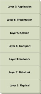
Basic switches (IEEE Std 802.1D) operate at layer two (L2) of the OSI model. See Figure 5-2. The OSI model, or standard, is the guideline for technology manufacturers who strive to build interfaces with other network technologies. While most of our ASR discussion in Chapter 4 focused on layers four through seven, switch and VLAN technology center on layers two and three.
Figure 5 - 2: The OSI Model
Ethernet D-switch packet forwarding
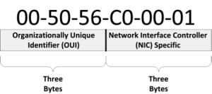
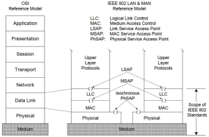
The component at L2 involved in switching is medium address control (MAC). Each network interface possesses a physical, or MAC, address. The manufacturer assigns this six-byte value. IEEE Std 802.2001 specifies the format of the address and additional data link layer components. As shown in Figure 5-3, it consists of two parts. The first three bytes identify the manufacturer. Figure 5-4 depicts how 802.2001 maps to the data link layer. Every device connected to a network must have a MAC address. If it does not, no other device can establish a session with it.
Figure 5 - 3: Basic MAC Address Format
Address resolution protocol
When a computer needs to communicate with another network-attached device, it sends an address resolution protocol (ARP) broadcast. This assumes the IP address, for example, of both devices possesses the same network identifier. For example, if the target device and the source device both have the network address 192.168.10.0/24, the source device safely assumes the target device is on the same network or network segment. The broadcast packet travels to all devices on the same network segment asking for a response from the device with the target IP address.
An 802.1D (D-switch) receives a broadcast packet and sends it out all ports except the one on which it is received. See Figure 5-5. The first issue is packet delivery to all devices. This unnecessarily increases network traffic and degrades performance. The second issue is visibility. The desktop device in our example can find any connected device simply by sending one or more ARP broadcasts. A D-switch enables maximum visibility because it cannot determine whether a requesting device is authorized to see or contact the target device. Further, all devices exist on the same network segment.
Figure 5 - 4: IEEE 802.2001 Data Link Mapping (IEEE, 2002)
If a device with the target IP address exists on the network, it picks up and processes the broadcast packet. Using the source MAC address in the broadcast packet sends a response to the requesting device that includes the target’s MAC address. Once the source device receives the target’s MAC address, it begins the process of establishing a session.
Figure 5 - 5: D-switch ARP Broadcast
The CAM
Switches use a content addressable memory (CAM) table to track MAC address/port pairs. For example, when a device connected to switch port 10 sends its first packet, the switch updates the CAM table with the port and the MAC address. From the time of the update through the entry’s aging period, the switch forwards all packets with the device’s MAC address as the target through port 10.
Aging is a process in which a switch deletes address/port pairs from its CAM table if certain conditions are met. For example, an entry might be removed if the switch has not received packets from a device for a specified period. Many switches are configurable so the CAM table port/address entries do not age. This is an important security consideration, as demonstrated later in this chapter.
Adding VLANs
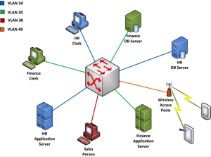
In addition to reducing network traffic, 802.1Q compatible switches (Q-switches) add the ability to segment a flat network into separate broadcast domains. Figure 5-6 shows how a single switch might manage four collections of devices.
A VLAN is a set of switch ports. In our example, the HR clerk and the HR servers are assigned to switch ports 2, 4 and 8. Ports 2, 4 and 8 are configured as VLAN 10. Devices connected to these ports can talk to each other, but they are logically isolated from devices connected to ports not part of the VLAN 10 set.
Figure 5 - 6: Basic VLAN Configuration
In this scenario, the salesperson’s desktop on VLAN 30 is unable to communicate with any other devices on the network. If the computer sends an ARP broadcast requesting the MAC address of the HR application server, for example, the request never reaches VLAN 10. Because the desktop cannot obtain the server’s hardware address, no connection is possible. This example demonstrates how we can separate collections of users, servers, and other devices into smaller network attack surfaces.
Private VLANs
A specialized type of VLAN is a private (isolated) VLAN. When a VLAN set is configured in this way, none of the ports in the VLAN set can communicate with each other. In situations such as an externally facing security zone, we often want servers to communicate with users from other VLANs, but security is strengthened by preventing the servers from establishing sessions with each other. We take a closer look at this in the final security zone section.
VLAN tagging
Although not needed for our simple example, the rest of this chapter requires an understanding of VLAN tagging. The 802.1Q standard can also be called a tagging specification. When a VLAN segmented network consists of only one switch, tagging is not necessary. The single switch knows the port a packet is received on; based on the switch’s CAM, it also knows the VLAN to which the packet belongs and the other ports related to it. However, things can get more complicated if multiple switches exist, or if all packets, regardless of VLAN membership, must travel over one or more aggregated paths (trunks).
802.1Q specifies the format for a VLAN tag to ensure packets, no matter where they travel, always make it to the proper VLAN or trunk ports and only those ports. Figure 5-7 depicts the location of the tag in an ethernet packet. The tag consists of four bytes divided into two fields. VLAN protocol ID contains the value of 0x8100 if tag control info contains information about the VLAN to which the packet belongs. It looks simple, but it is not always compatible with existing devices.
Figure 5 - 7: Ethernet Packet with VLAN Tag
The 802.1Q information is inserted into the ethernet packet. This extends the packet and creates additional information that VLAN-unaware devices cannot process. Cannot-process equals errors and dropped packets. Most D-switches offered today can process a tagged packet even if it does not know how to process the tag. However, the vast majority of end-point devices will not. As we examine later in this chapter, tag removal is part of the packet forwarding process.
Configuring VLANs
Packets belong to VLANs, not devices. Each packet arriving at a VLAN-configured Q-switch is checked to see if it meets the criteria for belonging to any of the connected LANs. An administrator can use any of several approaches for VLAN configuration:
- Port assignment
- MAC address
- IP subnet
- Dynamic assignment
- Device assignment
- Protocols
- Applications
Port assignment
The default method specified in 802.1Q is to assign ports explicitly to VLANs within the switch. In our previous example (Figure 6), any packet entering through port 2, 4 or 8 is automatically assigned to VLAN 10. If I want to increase the number of users on the VLAN, I might attach the HR clerk’s desktop to a hub and the hub to the switch. Any additional desktop I attach to the hub is also automatically a member of VLAN 10.
MAC address
An administrator can build a table of MAC address/VLAN pairs within the switch. When a packet arrives, it is parsed to retrieve the source MAC address and assigned to the appropriate VLAN. While this can require significant management effort, it is a way to maintain VLAN membership for devices that frequently move; regardless of where they move or how they connect, each will always be assigned to the appropriate VLAN. A security vulnerability with this approach is MAC address spoofing. It is easy for an attacker to spoof a valid MAC address to gain access to the VLAN.
IP subnet
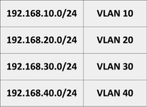
VLANs are network segments. As such, we can assign each VLAN an IP address scope. See Table 5-1. I used the third octet. As with MAC address assignment, the Q-switch parses a packet, locates the source IP address, and assigns the packet to the appropriate VLAN. Since no routing is set up at this point, packets are forced by address to communicate only with devices on the same VLAN.
Table 5 – 1: VLAN Subnet Assignments
Dynamic assignment
One approach particularly useful for wireless or remote devices is dynamic VLAN assignment. It is based on the authenticating user’s group membership as managed by a service, usually consisting of RADIUS and a user directory. Once the user is authenticated, packets from his device are assigned to the appropriate VLAN based on rules set up by the administrator.
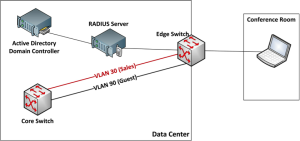
Dynamic VLAN assignment also adds security for shared wired VLAN ports, as shown in Figure 5-8. For example, if a salesperson connects her laptop to an ethernet jack in a conference room, the switch requires hardware and user authentication. Once the RADIUS server receives a user ID and password, it uses an active directory to determine the group to which the user belongs. Because she belongs to the sales group, she is assigned to the sales VLAN. If a vendor or other non-employee connects to the same port, authentication is not possible, and the device is assigned to the guest VLAN.
This is a flexible approach and works well with role-based access control. If the salesperson in our example moves to project management, her AD account changes groups. The next time she authenticates, she is automatically denied access to the sales VLAN and included in the project management VLAN.
Figure 5 - 8: Dynamic VLAN Assignment
Device assignment
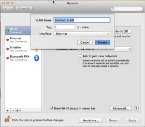
Most end-point devices are not VLAN-aware. In other words, they are unable to process incoming tagged packets or tag a packet before sending it out to the network. However, manufacturers like Intel provide extensions to selected NIC drivers to provide this functionality. Further, Apple includes VLAN tag management in Mac OS X Snow Leopard and Lion operating systems. Figure 5-9 is a screenshot from my iMac running Lion. I can assign each of my interfaces to a different VLAN, if necessary. Any packet leaving a VLAN-configured end-point network interface card contains the proper VLAN tag.
Protocols
Some networks run multiple network protocols, adding IPX and AppleTalk to the mix. If configured to do so, Q-switches assign packets to VLANs based on the protocol used.
Applications
Switches or end-point devices supporting this capability can assign a packet to a VLAN based on the nature of the packet payload. For example, packets part of a streaming video application might be relegated to a specific VLAN. This reduces traffic on VLANs handling normal business. Another benefit of application-based assignment is the ability to assign various packets from the same system to a variety of VLANs based on the applications used. This allows user authentication and authorization to determine VLAN assignments and the consequent restrictions imposed.
Figure 5 - 9: iMac VLAN Assignment
The advantage of having VLAN-aware end-point devices is significant. An organization can create device images for each VLAN based on user role. When an image is applied to a device, that device will connect to the appropriate VLAN no matter where or how it connects. This is done without the headaches associated with approaches like MAC address management. However, explicit end-point VLAN assignment lacks the flexibility of approaches like dynamic VLAN assignment.
Trunking
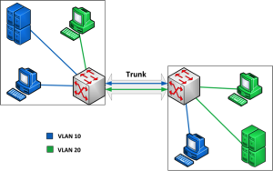
Many organizations have more than one switch. Further, VLANs are not dependent on the actual location of an end-point device or switches. Refer to Figure 5-10. When using two Q-switches to manage VLANs, a trunk is configured between them using a port on each switch: a trunk port. During a broadcast, all VLAN packets entering either switch are sent via the trunk to the other switch. This allows VLAN members to exist in different locations and still use all VLAN-assigned resources.
Figure 5 - 10: Trunking
VLAN access control list (VACL) filtering
Q-switches can use two types of access control lists: basic access control lists (ACLs) and VACLs. ACLs filter packets entering an L2 interface. An administrator can configure filtering at one of two levels: standard or extended. Standard IP, for example, simply checks the source address. Extended IP checks both the source and destination IP addresses. Further, extended filtering can also check protocols. If a defined control list entry denies a certain source/destination/protocol set, any packet containing it is dropped. ACL extended IP filtering is a useful option for trunk ports.
ACLs work well, but they cannot filter traffic within a VLAN; this is the role of a VACL. VACLs are assigned to VLANs. Once assigned, a VACL filters all traffic entering the VLAN or passing between same-VLAN members. Intra-VLAN filtering only works if the packets to be checked pass in route through a port on a switch containing relevant VACL configurations.
Both ACLs and VACLs are valuable security controls. Packets not authorized to pass are dropped. However, ACLs and VACLs are mutually exclusive by port. In other words, an ACL and a VACL cannot exist for the same switch port. In addition to L2 filtering, ACLs and VACLs provide packet filtering for the layer three (L3) switch virtual interfaces (SVIs) examined later in this chapter.
Finally, the switch checks access control lists from the top-down, applying the first match it finds based on the packet content. If no match is found, a default deny is usually applied, and the packet is dropped.
Q-switch packet processing
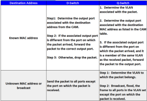
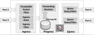
Before expanding our discussion to multiple switches and inter-VLAN routing, let us take a closer look at the internal processes involved when a Q-switch encounters a packet. First, Table 5-2 provides a high-level look at the expected outcomes. Again, this looks simple, but a switch works rather hard to manage VLAN accessibility. The detailed processes through which a packet passes in a VLAN-configured Q-switch include ingress, progress and egress. See Figure 5-11.
Table 5 - 2: High-level Switch VLAN Packet Processing
Ingress
A packet entering a VLAN-aware Q-switch is first submitted to the relevant acceptable packet filter (APF). It must pass this test before the switch performs any detailed filtering. The APF is configured in one of two ways: admit all or admit all tagged. If configured to admit all, all incoming packets move immediately to ingress rules assessment. This is a necessary configuration for end-point device ports on an edge switch. They must initially accept all packets unless all devices connected to them are VLAN-aware.
An admit all tagged configuration allows only VLAN-tagged packets to pass, which is a common configuration for a trunk port. All other packets are dropped. Further, an administrator can configure trunk ports to allow only packets from specific VLANs, thereby pruning unwanted traffic.
Figure 5 - 11: Q-Switch Packet Forwarding Process (Seifert & Edwards, 2008)
If a packet makes it through the APF, the switch applies relevant ingress rules. It is here that a packet is mapped to one, and only one, VLAN. If the packet is already VLAN-tagged, no additional rules need apply. The packet moves to the relevant ingress filter. However, packets without tags receive a VLAN assignment based on one or more of the criteria listed above in configuring VLANs.
After being assigned a VLAN, the packet moves to the relevant ingress filter. It is here the switch applies a relevant access control list. Again, the list is checked from the top down with the first match applied. The switch drops the packet if no match is available. Passing the ingress filter, the packet moves to the progress process.
Progress
The progress process maps the incoming packet to relevant output ports. In a D-switch, the destination MAC address determines whether the packet is sent out through single or multiple switch ports. In a VLAN-enabled Q-switch, the target address is coupled with the VLAN identifier to determine relevant output ports for packet egress. Upon assigning the ports, the packet travels through the internal switch fabric to single or multiple destinations.
VLAN information in the filtering database (CAM table) used in this process is updated either manually or automatically, depending on the switch configuration. We look at the update process and associated security considerations later in this chapter.
Egress
Because not all devices are VLAN-aware, the egress rules determine whether to send the packet with or without the VLAN tag. Unless every member of the target VLAN connected to the egress port is VLAN-aware, the switch must strip the tag and recalculate and apply the packet’s frame check sequence (FCS). It is also possible to insert a tag at this point, particularly if the packet is untagged and the egress port is one side of a trunk. After making the tag decision, the switch applies the egress filter.
The egress filter makes one final check to ensure the packet is “authorized” to exit the assigned port. For example, stripping the VLAN tag might inadvertently render the packet unusable by the switch logic. In addition, automated switch VLAN port sharing might provide information inconsistent between the ingress filters/rules and what the egress filter knows about the network.
The native VLAN
When you take a Q-switch out of the box, all ports are assigned to the native VLAN: usually VLAN 1. If you do not reassign ports to VLANs, they remain assigned to VLAN 1. This is fine if you are not segmenting your network for security purposes. However, allowing data to travel over VLAN 1 when you have other options is bad security.
Packets not assigned to VLANs travel over VLAN 1. They typically contain management and control information. Consequently, when you segment your network, remove all data ports from VLAN 1. If a port is used, assign it to the appropriate VLAN. If not used, assign it to an unused VLAN until you need it. For example, you might reserve VLAN 99 for all unused ports.
Expanding VLAN architecture
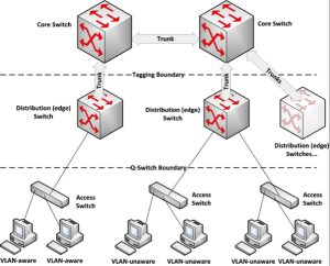
So far, we have looked at flat switch architecture. In Figure 5-10, for example, we have two peer switches performing the same functions. However, larger implementations benefit from a multi-tier architecture, as shown in Figure 5-12. This is a basic example without redundant links or spanning-tree challenges.
Figure 5 - 12: Tiered VLAN Architecture
The bottom tier is the access layer. In our example, these switches are not VLAN-aware; think of a Linksys switch layer that does nothing but connect devices with separate collision domains. However, they can transparently pass tagged packets between connected components. The model contains four VLAN-unaware and two VLAN-aware end-point devices separated on different edge switch ports.
A common configuration is to place VLAN-aware switches at the access layer and assign VLANs there. An organization’s switch infrastructure design is usually based on what infrastructure is available, business need and cost. In any case, try to keep aware and unaware devices separate. This makes less work for the switches and the administrator.
Each access tier switch is connected via a trunk to an “edge” switch in the middle, distribution tier. An edge switch performs VLAN assignment and tagging, applying all rules and filters listed in Q-switch packet processing. Distributing the load across the distribution tier and keeping it from the core can optimize performance. However, more recent switches do this with specialized hardware and suffer no performance degradation, allowing core switches to perform these operations, too.
VLAN-tagged packets pass to the core switches via configured trunks shared with the edge switches. The core switches do not tag packets. Further, all devices connected to the core tier switches are VLAN-aware, so no tag stripping is necessary. In most cases, you will configure data VLAN ports in the core to drop any packet that is not tagged. The core is designed for high-speed forwarding of packets within a facility, across campus and more.
VTP and MVRP
Multiple registration protocol (MRP), defined by IEEE 802.1ak, operates at L2 and enables switches to register and deregister attribute values. An MRP application, multiple VLAN registration protocol (MVRP), distributes VLAN identifiers. It allows an administrator to configure a VLAN on one switch and rely on automatic propagation of the configuration to all other MRP-enabled Q-switches in the network. However, it can cause problems if not properly configured.
Virtual trunking protocol (VTP) is Cisco’s proprietary alternative to MVRP and its predecessor, GVRP. I am taking a short detour from my intent to make this book vendor-neutral because MVRP is not implemented consistently across all VLAN implementations. Vendors, like Cisco, have their own methods of replicating information. However, the challenges included here are commonly found in many VLAN replication schemes.
VTP runs only over trunks and requires configuration on both sides. Minimally, failures to ensure all Q-switches are aware of a VLAN or its current configuration results in dropped packets and an inability to connect to required resources.
Attackers or hapless users can leverage VTP, either intentionally or accidentally, to cause a widespread denial of service attack (DoS). This is possible because of the way VTP propagates information. The new configuration advertises its change sequence number. For example, the first change to the network VLAN configuration has a sequence number of 1, change 2 has a sequence number of 2 and so on.
By default, when a VTP-enabled switch receives an advertisement, it compares the change sequence number to the sequence number of the last change. If the advertised number is higher than the number recorded in the switch, the switch flushes the old configuration and replaces it with the new one. This works well until someone attaches a rogue switch with a higher sequence number. When that happens, the old configuration is flushed across all switches; the network stops working.
One way to mitigate this risk is turning off VTP across all switches. This is probably the best solution for small networks, but manually managing changes across large networks is much easier with VTP enabled. A second alternative is the VTP configuration of each switch based on its function, limiting which switches can create or distribute VLAN changes. The options include:
- Server: the default configuration. It provides a switch with the ability to change VLAN configurations, sends and receives updates, and saves VLAN configurations. Configure core switches as servers. Make all changes on the core switches, which distribute the changes across the network.
- Client: a client cannot change VLAN configurations, but it can send and receive updates. It is also prohibited from saving VLAN configurations. Configure edge switches as clients.
- Transparent: in transparent mode, a switch can change VLAN information and allows changes to pass through on their way to other switches. However, it does not listen to VTP advertisements. The switch can save VLAN configurations.
You can also prevent unwanted changes by requiring authentication. None of us would ever make a mistake and load the wrong configuration. Regardless of how you configure VTP, it remains an unnecessary risk to your network. Cisco recommends turning it off; implement a documented VLAN management process, integrated into your change management activities, to ensure proper propagation of changes.
Inter-VLAN routing
VLANs segment a network and maintain isolation between segments. But what if a device on one VLAN must communicate with a device on another VLAN? The only way to enable this is via L3 routing using one of two approaches: the use of an external router or the configuration of Q-switch SVIs (switch virtual interfaces). Both prefer IP addressing for VLAN membership assignment.
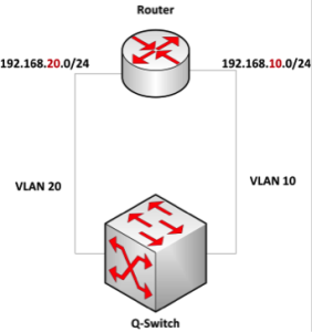
Using a router
Inter-VLAN routing with a router is very simple. As shown in Figure 5-13, each VLAN’s traffic passes through an assigned router port. The default gateway for connected devices is the VLAN’s router interface. In our example, I would assign the router interface addresses of 192.168.20.1 and 192.168.10.1. This works if you have spare router ports and minimal need for inter-VLAN routing. However, it does not scale.
Figure 5 - 13: Basic Inter-VLAN Routing
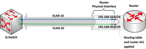
A better approach is using what is often called a router-on-a-stick or a one-armed router. It requires a router capable of trunk port configuration with support for sub-interfaces. Figure 5-14 depicts how this works. A trunk is configured between the Q-switch and the router. The router is configured with multiple sub-interfaces, one for each of the routed VLANs. Connected devices use the relevant sub-interface address as the default gateway. The routing table is applied to packets entering the sub-interfaces. Depending on the router, this configuration can support 4096 sub-interfaces.
A new routing concept is introduced here: the router (L3) ACL. In addition to controlling packets with L2 ACLs and VACLs, an administrator can add ACLs to control traffic routed between VLANs. This also applies to virtual L3 interfaces in Q-switches.
Figure 5 - 14: Inter-VLAN Router Sub-Interface Routing
Using an L3 switch
If you want to minimize physical router use, Q-switches capable of L3 routing are a good solution. Q-switch routing includes creating multiple SVIs, assigning them to subnets and maintaining a routing table. Again, the connected devices use the relevant SVI as their default gateway. In addition to L2 access control lists, you can apply an additional L3 ACL to control packets passing from one VLAN to another. An L3 ACL is a good additional layer of security in support of VACLs.
VLAN security
We already looked at segmentation and the use of access control lists to protect system attack surfaces. However, switches and the VLANs they manage each possess their own attack surface. Out-of-the-box, most Q-switches are not ready to help protect anything.
Physical security
The first step in securing a switch is restricting physical access. Make sure it is behind a locked door. Under no circumstances should unauthorized people gain physical access to it or any other infrastructure equipment.
Password access
Under no circumstances should remote or local access be password-free. For example, configure secure shell (SSH) or Telnet ports for password-only access. Further, access should conform to the roles performed by each person with management responsibilities.
Role-based access control
In many organizations, privileged access to a switch means full access. Regardless of role, each administrator can perform any management task on the device. This is never a good idea. Instead, configure the switch so that each user has a unique login and password. In addition, assign privilege levels based on the user’s role in switch administration. No more than one or two administrators should have full access. Finally, configure password encryption.
In addition to access controls, make sure accounting is properly configured and integrated into your log management processes. Accounting tracks all configuration changes by an authenticated user. Knowing who did what and when is valuable if something breaks or the network behaves in unexpected ways.
Once you take these basic steps, it is time to begin looking at secure configurations for VLANs. Most, if not all, successful attacks against VLANs are the result of poor switch configuration.
VLAN pruning
Allow only relevant VLANs to use each trunk. If you know there is no reason for a broadcast packet from VLAN 1, for example, to move over a specific trunk, block it.
MAC flooding defense
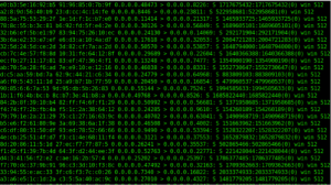
A common VLAN attack is a CAM table overflow. As we saw earlier in this chapter, the Q-switch CAM table contains port/MAC address/VLAN assignments. We also saw that table entries age and are removed to make room for more active devices. A packet without address information in the table causes the switch to perform an ARP broadcast to determine the port through which to send the packet. If the table fills up, however, all incoming packets are sent out to all ports, regardless of VLAN assignment. This essentially turns the switch into a hub.
An attacker exploits this vulnerability by continuously sending a large number of spoofed MAC addresses to the switch, filling the CAM table (see Figure 5-15). Programs like dsniff provide this capability. As actual entries age, the switch replaces them with one from the continuous flow of attack packets. Once the switch begins flooding packets out of all ports, the attacker can extract data or take advantage of the opportunity and spoof one or more MAC addresses. This ARP spoofing allows the attacker to maintain some access after the flooding attack ends.
Figure 5 - 15: MAC Flooding Attack
Preventing MAC flooding requires performing one or more port security steps:
- Manually bind one MAC address to each port
- Use 802.1x to force packet filtering
- Configure the switch to learn the first n MAC addresses appearing on each port, and cause the switch to write them to the running configuration
Once port security is enabled, a port receiving a packet with an unknown MAC address blocks the address or shuts down the port; the administrator determines what happens during port-security configuration.
VLAN hopping defense
VLAN hopping is an umbrella term representing any unauthorized VLAN access that uses one VLAN or trunk to access data on another. The two most common VLAN hopping attack vectors are dynamic port configuration and double tagging.
Dynamic port configuration
Q-switches often provide dynamic port configuration. This allows a switch to either configure a port as an access port or a trunk port. An access port is any non-trunk port in a VLAN set. Superficially, this seems like a good idea. The dynamic trunking protocol (DTP) is designed specifically for this. If one Q-switch sends a DTP request to another Q-switch, a trunk is automatically created on the relevant port. This is great if not maliciously used.
An attacker using DTP can easily gain access to all VLAN traffic. First, a desktop or laptop is attached to a switch port. Any open port in the organization will suffice. Spoofing a Q-switch, the attacker sends a DTP request to the target Q-switch. If dynamic port configuration is enabled, the target grants the request and configures the attacker’s port as a trunk. All VLAN traffic destined for trunk output from the switch now also flows to the attacker’s computer.
Preventing this attack requires two simple steps:
- Before you connect your switch to the network, configure all ports on edge switches as access ports. Manually configure trunk ports as necessary.
- Again, ensure all unused, connected ports are assigned to an unused VLAN.
Double tagging
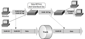
Double tagging also uses DTP. The attacker sends a packet with two VLAN tags over a malicious trunk created in the same way a MAC flooding attacker would. As shown in Figure 5-16, the first Q-switch strips the VLAN 10 tag and sends the packet back out. The second switch sees the packet as belonging to VLAN 20 and sends it to all appropriate ports. The defense is to not use DTP and initially to set all switch ports to access ports on all edge switches.
Figure 5 - 16: 802.1Q Double-Tagging (Seifert & Edwards, 2008)
Implementation process
We have covered a lot of concepts in this chapter. It is time to put it all together into an implementation plan: a plan that provides architecture-specific segmentation and safe switch operation. The process consists of the following:
- Configure all ports as access ports
- Configure switch security
- Control physical access
- Create role-based user accounts
- Restrict telnet ports to account- and password-only access
- Enable port security
- Configure trunks
- Configure VTP/MVRP (recommended to shut it off)
- Create VLANs
- Assign an IP address range to each VLAN
- Assign ports to VLANs
- by IP address (recommended for most static wired networks)
- by MAC address
- by port assignment
- by dynamic assignment (recommended for most wireless networks and shared switch port networks)
- by protocols
- by applications
- Remove all data VLANs from the native VLAN
- Assign unused, connected ports to an unused VLAN
- Configure inter-VLAN routing
- Create and apply L2 ACLs and VACLs
- Create and apply L3 ACLs
Security zones
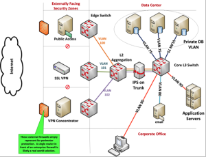
To demonstrate a real-world model of how you might use VLANs, I created a fictional zoned network. In Figure 5-17, I isolated incoming internet traffic and created internal data center security zones.
Figure 5 - 17: Security Zones
Server and external traffic isolation
A security zone is nothing more than a network segment with protected ingress. The level of protection is commensurate with the criticality of systems or the sensitivity of data it contains. One type of security zone provides a secure bridge between the internet and the data center. Note that the externally facing zones cannot communicate with each other; each is a separate VLAN, and no routing is allowed between them. VLAN assignments and access control list processing occur in the edge switches. The edge switches trunk to an L2 aggregation switch.
Aggregating external traffic allows implementation of single-point packet, session and network behavior monitoring. Placing all incoming packets on a single trunk allows proactive response before any traffic arrives at the core. For example, all packets passing through the aggregator-to-core trunk pass through an intrusion prevention system (IPS).
Reaching the L3 Q-switch, I route packets by the routing table and constrain packet access with VACLs and L3 SVI ACLs. In addition, the database server VLAN is private. Although application servers communicate with required servers in VLAN 75, the database servers are prevented from communicating with each other.
Finally, users in the corporate office are on the same VLAN as the application servers and are routed to VLAN 80 for email. External devices cannot establish sessions with end-user devices. Because routing is controlled via routing tables, ACLs and VACLs, access to critical systems and data is limited by separation of duties, least privilege and need-to-know.
Voice over IP (VoIP)
Another common use for VLANs is the separation of IP phone (VoIP) traffic from data segments. Leveraging another portion of the 802.1Q tag, Q-switches can also prioritize packets based on a quality of service (QoS) value, as shown in Figure 5-18. IP phones are usually VLAN-aware, inserting the VLAN tag before placing a voice packet on the network. Voice packets should use non-data VLANs for optimized QoS and security.
Figure 5 - 18: Priority (QoS) Tag
Allowing only IP phones on a voice VLAN helps prevent an attacker connecting a computer to an open port from collecting voice packets for later analysis. Applications like Wireshark and Voice Over Misconfigured Internet Telephones (VOMIT) enable the conversion of conversations to .WAV files (Cioara & Valentine, 2012). Proper configuration of switches and VLANs, as described in VLAN hopping defense, helps prevent most voice VLAN attacks.
Using VLAN-aware IP phones, the switch administrator can explicitly assign VLANs to voice packets. All voice packets received by the switch port already have a VLAN assignment, and the switch forwards them accordingly. If you attach a computer to an ethernet port on the phone, data packets arrive at the switch port untagged. VLAN assignment of data packets is controlled by the assignment rules you configured for the VLAN to which the port/packet belongs. What you end up with is a Q-switch port that handles both tagged and untagged packets. While usually configured as an access port, it behaves like a mini-trunk.
How to best approach VLAN
System attack surfaces are not perfect. Consequently, we should allow only expected traffic to reach them. VLANs provide this capability. By using VACLs, entry into each VLAN is tightly controlled, and the use of L3 ACLs helps ensure only authorized packets route between VLANs.
Routing between VLANs is necessary. However, if all VLANs end up routed to all other VLANs, something is wrong in your architecture, and the benefits of network segmentation diminish.
Securing VLANs includes both switch security and proper VLAN configuration. The most common attacks against VLAN technology, VLAN hopping and double 802.1Q tagging, are preventable with proper attention to configuration best practices. In addition, consider not using VTP or other automated VLAN registration technology. The risk usually exceeds the benefit.
Send voice and data traffic via separate VLANs. Protecting voice packets requires the same diligence as that applied to securing data VLANs. Further, VLAN QoS tagging ensures switches process voice traffic first to avoid performance issues.
Finally, enhance network segments by making them security zones. A VLAN by itself is not a security zone. Rather, a VLAN with appropriate monitoring and filtering eventually becomes a security zone.
Sources:
Cioara, J., & Valentine, M. (2012). CCNA Voice 640-461: Understanding the Cisco IP Phone Concepts and Registration. Indianapolis: Pearson Education, Cisco Press.
IEEE. (2002). IEEE Standard for Local and Metropolitan Area Networks: Overview and Architecture. New York, NY: The Institute of Electrical and Electronics Engineers.
Seifert, R., & Edwards, J. (2008). The All-New Switch Book. Indianapolis: Wiley Publishing, Inc.

