Security+: Technologies and Tools - Switches and Routers [DECOMMISSIONED ARTICLE]
NOTE: This article reflects an older version of the Security+ Exam – please see the current Security+ Certification page for the most up-to-date information.
Introduction
In any type of IT Infrastructure, the network component is of utmost importance. After all, it is at this level where all communications and data packet traffic transpires for employees and even individuals to access shared resources from a central server. There are many components that go into this, such as Firewalls, Routers, Switches, Hubs, Bridges, Virtual Private Networks, Network Amplifiers, etc.
However, in this article, we focus primarily on two specific devices, that you, the Security+ cert holder need to have a strong grasp of:
- Routers
- Switches
What a Router Is
A Router can be specifically defined as follows:
“A router is a device that directs data traffic along specific routes. A router sends information, such as email and the content of web pages, between your computer and the network server. A router is also the device that keeps single computers, or entire networks, connected to the internet.”
(SOURCE: https://www.digitalunite.com/guides/using-internet-0/connecting-internet/what-router)
Based from the definition, a Router essentially connects and communicates with all devices (such as the workstations, servers, and even the wireless devices) that are an in the internal network, such as the corporate intranet in an organization. From there, it also connects this intranet to the “outside world” so that network communications can transpire all over the world.
In a way, it is very similar to that of a network modem, which is very commonly used in home-based networks. For example, to get access to the Internet, the computer must be connected to this modem, whether it is hard-wired, or wireless. However, a Router is unique in the sense that it consists of other features that make it more sophisticated than that of the traditional network modem. For example:
- It forwards the data packets to the correct TCP/IP address of the device in question; a Routing Table is used for this very purpose.
- It provides network traffic segmentation, and also segregates amongst different multiple broadcast domains. This simply means that the Router can be used as an effective tool to divide up a complex network structure.
- It defines network layer addressing subnets. A subnet is a uniquely identifiable segment in an entire network.
- It also acts as a “Gateway;” meaning, it can connect the various subnets to together, and even be used to connect to a specific network that is outside of the internal network.
- It facilitates communications with another network that are non-Ethernet based, such as those that are based upon serial interfaces, DSL connections, and other forms of WAN connectivity.
- It can also act as a sophisticated Firewall, in that it examines for all incoming data packets. If any of them appear to be malformed or suspicious, it will discard them immediately before they can penetrate the corporate Intranet.
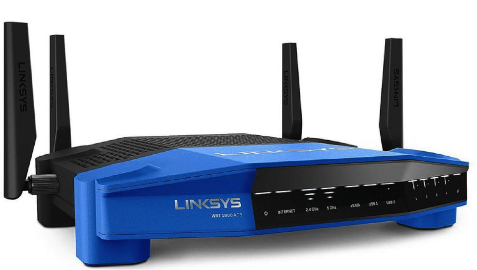
An example of a wireless Router can be seen below:
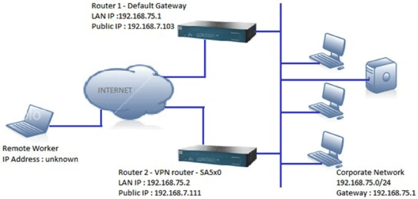
An example of a Router being used as a Gateway is illustrated below:
The Routing Table
As mentioned, one of the most critical functions of the Router is to send the network communications and its associated data packets to the proper device. This is done via the “Routing Table.” It can be technically defined as follows:
“A routing table is a data file that acts as a map and is often installed on a router. The routing table contains information about various routes between devices to present the most efficient paths for data packets.”
(SOURCE: https://www.techopedia.com/definition/15720/routing-table).
To illustrate this point, suppose that Company ABC is connected to the outside internet, and is located at Point A. A remote office is located at Point B, thousands of miles away. The remote employee at this location wishes to send a file to a co-worker at Point A. Once this message has been sent at arrives at the perimeter of Company ABC’s network, the Router will first inspect the data packets to make sure that there are no malformed or malicious ones.
If there are none, it will then accept these data packets that constitute the file and look up the destination TCP/IP Address of the recipient in the Routing Table. Once that has been determined, the Router will then transmit those data packets to the right device so that the file can appropriately receive and safely opened.
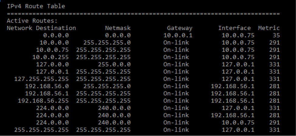
An example of a Routing Table as seen through the Command Line Interface is illustrated below:
What a Switch Is
A Switch can be technically defined as follows:
“A network switch is a networking device that connects devices together on a computer network by using packet switching to receive, process, and forward data to the destination device.”
(SOURCE: https://en.wikipedia.org/wiki/Network_switch)
In this regard, a Switch can be considered as a subcomponent to that of the Router. For example, it is the Router that connects Wide Area Networks (WANs) together, and it is the Switch that connects the Local Area Networks (LANs) together, and all the devices that reside in them.
To further illustrate, suppose that Company ABC has remote offices all over the world. These remote offices will be on a WAN that is different from the WAN that Company ABC is on. It is the Router that connects these separate WANs together.
Further, within a WAN, there will be smaller network segments (as mentioned, it is the subnet that uniquely identifies these segments) known as LAN’s. It is on the LAN that the various devices are networked amongst each other and communicate.
In our previous example, although the Router can send the file directly to the recipient based from the Routing Table, it will be much more efficient from a network optimization perspective to send to forward it to the Switch. Then from there, the Switch can then transmit that file to the correct recipient.
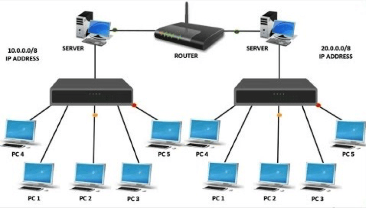
This is exemplified in the illustration below:
As can be seen, it is the switch that creates the network. From there, it is then the Router that connects the network by linking up the two servers together which are located in different WANs. It is important to note that a Switch should not be confused with a “Hub.”
In our previous illustration, the Hub would actually send that specific file to all of the devices that interlinked together in the same LAN. However, it is the Switch that can intelligently decide as to where the file needs to be forwarded (or sent) to a specific device. In this regard, a Switch is often referred to as an “Intelligent Device.”
In this regard, a Switch can also “learn” over time the Media Control Address (MAC) Addresses of each device that is networked to. A MAC Address is the actual physical address of the device in question, and the TCP/IP Address is the network address of it. The MAC Address is stored in what is known as a “Forward/Filter Table” in the Hub, which serves the same purpose as that of the Routing Table in a Router. As a Security+ cert holder, it is important that you establish the Switches in such a way that there is not only redundancy but also that you avoid what is known as a “Broadcast Storm.” This is defined as follows:
“A broadcast storm occurs when a network system is overwhelmed by continuous multicast or broadcast traffic. When different Switches are sending/broadcasting data over a [LAN] based network link, and the other network devices are rebroadcasting the data back to the network link in response, this eventually causes the whole network to meltdown and lead to the failure of network communication.” (SOURCE: https://www.techopedia.com/definition/6270/broadcast-storm).
This is often the result of a poorly designed and configured LAN, and even also because of poor network management and monitoring as well. Making sure that the LAN is thus properly and configured will avoid this problem, and this is also technically known as “Network Loop Prevention.”
Also, on a theoretical note, Switches can operate at the Level 2 of the OSI model, which is known as the “Datalink Layer.” This is where a device is directly connected to a Switch. It can also operate at Level 3 of this model, which is known as the “Network Layer,” in which a Switch can also be used to connect two or more LAN based networks together as well.
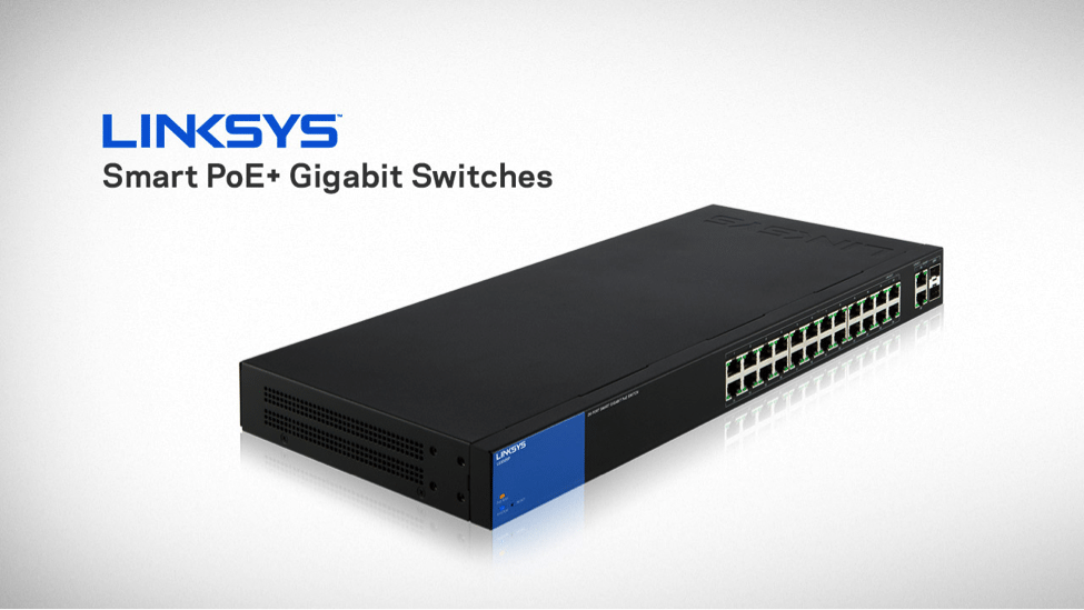
An illustration of what a Switch looks like is below:
Conclusions
Overall, this article has examined the important concepts behind Switches and Firewalls, that you the Security+ cert holder need to have a total understanding of.
However, if you are planning to take this cert, the following links will prove useful to you:
https://www.professormesser.com/security-plus/sy0-401/routers-firewalls-and-switches-2/
https://www.linkedin.com/learning/comptia-security-plus-sy0-401-cert-prep-network-security/switches-and-routers
https://quizlet.com/175347087/comptia-security-1-flash-cards/
http://comptiaexamtest.com/Security+SY0-401/tag/switch/page/2/
Sources
- https://www.digitalunite.com/guides/using-internet-0/connecting-internet/what-router
- https://searchnetworking.techtarget.com/definition/subnet
- https://www.techopedia.com/definition/15720/routing-table
- https://en.wikipedia.org/wiki/Network_switch
- https://broadcaststormblog.wordpress.com/2016/03/30/1-1-purpose-and-functions-of-network-devices-routers-switches-bridges-and-hubs/
- https://www.safaribooksonline.com/library/view/ccent-cisco-certified/9781118435250/chap07-sec005.html
- https://www.techopedia.com/definition/6270/broadcast-storm

