Instructions in x86 assembly
Introduction
This article will define three main categories of instructions in the x86 architecture. It will give examples in each of these categories and then show simulations on how some instructions are executed.
This article is designed for professional and self-starters who want to gain a detailed understanding of x86 instructions. Learning x86 instructions will help you to understand the make-up of underlying systems which popular programming languages conceal from you.
Intro to x86 Disassembly
Instructions in x86
Instructions can be defined as the language used to command a computer architecture. The x86 instructions basically tell the processor what to do. They are generally categorized into:
- Arithmetic and logic instructions
- Control-flow instructions
- Data movement instructions
Arithmetic and logic instructions in x86
These instructions consist of arithmetic and logical operations. Arithmetic operation can be applied on numerical quantities to multiply, add, subtract or divide. The logic operations are basically the operations performed by logic gates and the main operations are AND, OR, XOR and NOT.
Arithmetic instructions
Basic instruction format
ADD operand1, operand2.
Operand1 is the destination operand and operand2 is the source operand. The destination operand can be either a memory location or a register. Operand2 is the source operand and can be a constant, a register or memory location.
Example 1:
- MOV AX, 77H ;Copy the hex value 77 to the accumulator
- ADD AX, 80H ; Add the constant hex value 80 to the value in the accumulator.
Operand 1: 0111 0111
Operand2: 1000 0000
Content of operand1 after ADD operation: 1111 01111
Note that there is no carry from the lower four bits (low nibble) to the higher four bits (high nibble). The Auxiliary or Adjust flag will not be set.
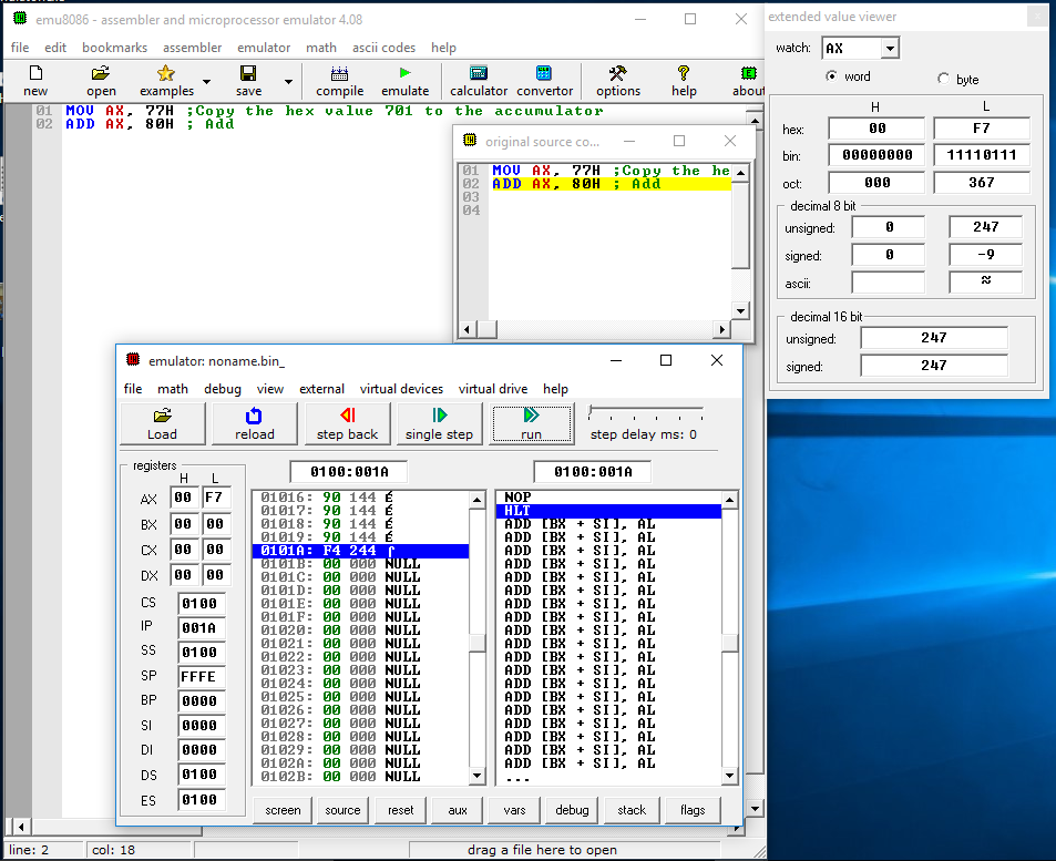
Figure 1: Contents of the accumulator (register AX) after ADD operation in example 1 is executed
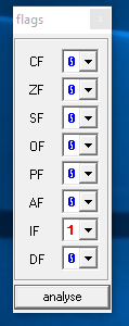
Figure 2. Status of flags after AND operation in example 1 is executed
Operation to execute: ADD AX, 80H
AX = 77H
Operation = 77H + 80H
Result = F7H
AX = F7H = 0000 0000 1111 0111b
Flag ZF = 0 ; result is not zero
Flag CF = 0; There is no carry from AL to AH
Flag SF = 0; Result is not negative (signed)
Flag OF = 0; Both operands were 8 bits long. Results is also 8 bits long. There is no overflow.
Flag PF = 0; The number of set bits in the result is 7, which is odd. PF is set when the number of set bits is even.
Flag AF = 0; There is no carry from low nibble to high nibble.
Flag IF = 1; This means the processor is capable of handling interrupts. Otherwise the interrupts are ignored.
Flag DF = 0; The Direction flag controls the right-to-left or left-to-right direction of string processing. When set to 1, the string is processed from highest to lowest address, Otherwise, strings are processed beginning from lowest to highest address.
Logical instructions
Basic instruction format
AND operand1, operand2
OR operand1, operand2
XOR operand1, operand2
NOT operand
For AND, OR and XOR instructions, operand1 is the destination operand and operand2 is the source operand. The destination operand can be either a memory location or a register. Operand2 is the source operand and can be a constant, a register or memory location. NOT instruction operands can either be a memory location or a register.
Example 2:
- MOV AX, 77H ;Copy the hex value 77 to the accumulator
- XOR AX, 80H
Operand 1: 0111 0111
Operand2: 1000 0000
Content of operand1 after XOR operation: 1111 0111
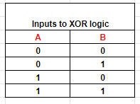
Table 1: Possible states for two inputs
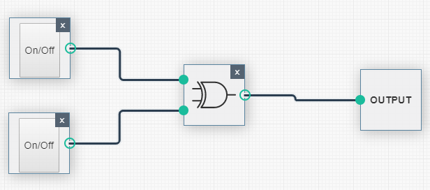
Figure 3: The XOR logic has an OFF state when both inputs are OFF
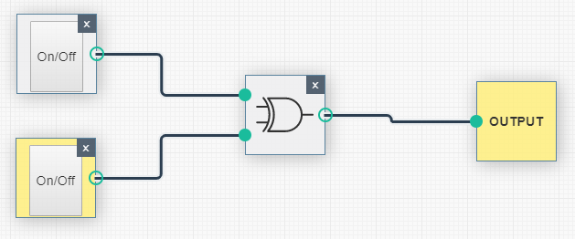
Figure 4: The XOR logic has an ON state when only one of the inputs are ON
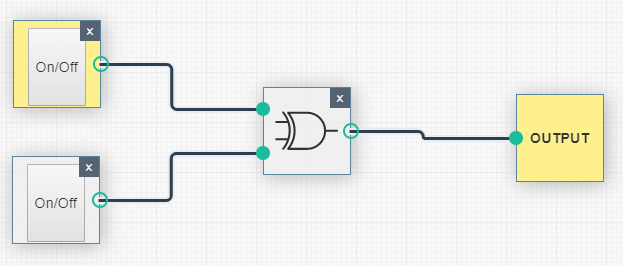
Figure 5: The XOR logic has an ON state when only one of the inputs are ON
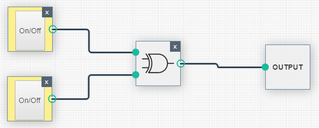
Figure 6: The XOR logic has an OFF state when both inputs are ON
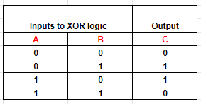
Table 2: Output of XOR logic with two inputs
Following from figures 3 to 6, it can be summarized that the XOR logic only returns true or 1 when either of the two inputs is ON. It returns 0 or shows an OFF state when both inputs are either 0 (OFF) or 1 (ON).
Control-flow instructions in x86
Control-flow instructions determine the next instruction to execute. The execution of control-flow operations does not allow sequential flow of the program. Control-flow instructions include conditional and unconditional jump instructions.
Jump instructions
Jumps are instructions that move control of the currently running program to a distant labelled instruction when a flag condition is met. Since status flags are sometimes modified by arithmetic instructions, jump instructions make use of them before execution.
Basic instruction format
JMP label
A label, either symbolic or numeric, refers to a memory location where an instruction is located. It is a convenient way of referring to an instruction in memory instead of referring to the memory address using an integer.
Example 3:
- JMP START:
- MOV AX, 77H
- MOV AX, 30H
- ADD AX, BX
- START:
- MOV AX, 100H
- MOV BX, 100H
In example 3, registers AX and BX will never be initialized with the values 77H and 30H respectively. As soon as the program starts, control is transferred to the instruction on line 5. Registers AX and BX only get the values 100H each.
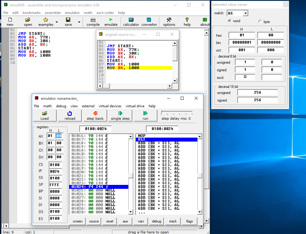
Figure 7: Content of register AX after the JMP instruction is executed
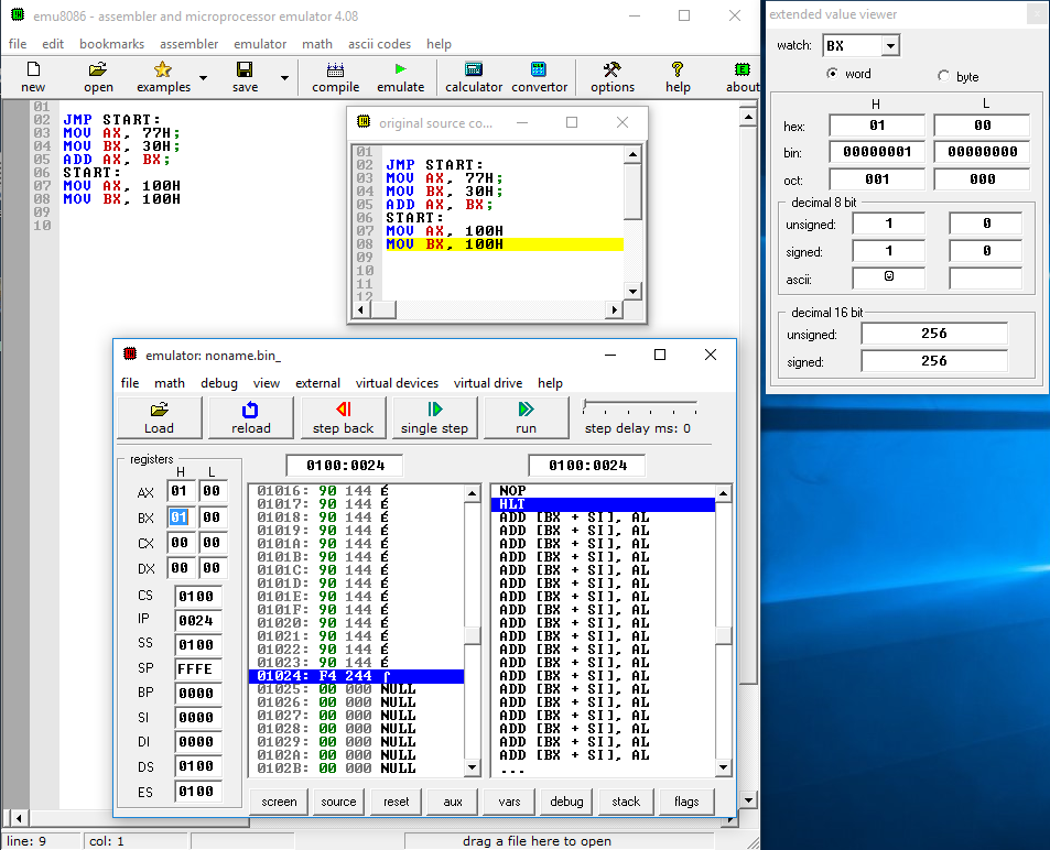
Figure 8: Content of register BX after the JMP instruction is executed
Data movement instructions in x86
Data movement instructions move data values from one location to another. The source and destination locations can be registers or memory. Data movement instructions include MOV, PUSH and POP among many others.
Basic instruction format
MOV operand1, operand2
Operand1 can either be a register or memory location. Operand2 can be a memory location, register or a constant value.
The MOV instruction moves the data item in the second operand into the first operand’s location. It is not possible to move data from one memory location to another memory location.
- PUSH operand1
Operand1 can be a memory location, register or a constant value
PUSH decrements the stack pointer by 2 if the operand-size attribute of the instruction is 16 bits; otherwise, it decrements the stack pointer by 4. PUSH then places the operand on the new top of stack, which is pointed to by the stack pointer.
- POP operand1
Operand1 can be a memory location or register
POP instructions perform the inverse operation of PUSH. It removes data from the stack and places it into the target register.
Conclusion
This article has explained the three main categories of instructions: arithmetic and logic instructions, control-flow instructions and data movement instructions. We’ve also shown simulations on how control-flow instructions and arithmetic and logic instructions are executed. These unique simulations show contents of specific registers and explains how status registers can be set during operations.
Intro to x86 Disassembly
Sources
- Instructions: Assembly Language, eceweb.ucsd.edu
- PUSH -- Push Operand onto the Stack, scs.stanford.edu


